
Page 302 - Softbound_Edition_19_en
P. 302
BP4x4
Spool valve BP4x4
TYPE CODE PERFORMANCE SPECIFICATIONS
2
B P 4 - # Oil viscosity u = 30 mm /s
Mounting interface acc. to Wandfluh standard Δp = f (Q) Pressure drop volume flow characteristics Volume flow direction
Hydraulically operated p [bar] Symbol P - A P - B P - T A - T B - T
30 K0101 J40 / Z40 3 3 - 2 2
Number of control ports 25 3 D41 3 3 - 2 2
20
Designation of symbols acc. to table D42 3 3 - 1 1
15 2 1
Sealing material NBR 10
FKM (Viton) D1 5
0
Design index (subject to change) 0 5 10 15 20 Q [l/min]
1.7-20
DIMENSIONS HYDRAULIC CONNECTION
GENERAL SPECIFICATIONS HYDRAULIC SPECIFICATIONS
Designation 4/2-, 4/3-spool valve Working pressure p = 350 bar
max 9.5
Construction Direct operated Tank pressure p T max = 90 bar 5.2
Mounting Flange construction Resp. 10 bar lower than the control MD= 5.2Nm 28
Nominal size NG4-Mini according to Wandfluh pressure 6 14
standard Maximum volume flow Q = 20 l/min, see characteristics
max
Actuation Hydraulically operated 35 30 G1/8" G1/8" 32 38 P
Ambient temperature -25…+70 °C Leakage oil See characteristics A B 14 27
Weight 0,69 kg Fluid Mineral oil, other fluid on request T T0
2
2
MTTFd 150 years Viscosity range 12 mm /s…320 mm /s
Temperature range -25…+70 °C (NBR) 10 20 30
fluid -20…+70 °C (FKM) MD=2.6Nm
Contamination Class 20 / 18 / 14 18 54 18
ACTUATION efficiency 91
Filtration Required filtration grade ß 10…16 ≥ 75,
Actuation Hydraulically operated see data sheet 1.0-50
Pilot pressure p = 10 bar PARTS LIST ACCESSORIES
min
p = 100 bar Position Article Description Fixing screws Data sheet 1.0-60
max
Control volume V = 0,16 cm 3 10 057.4600 Cover Threaded subplates Data sheet 2.9-10
30 246.1113 Socket head screw M4 x 12 DIN 912 Multi-station subplates Data sheet 2.9-50
50 160.2052 O-ring ID 5,28 x 1,78 (NBR) Horizontal mounting blocks Data sheet 2.9-90
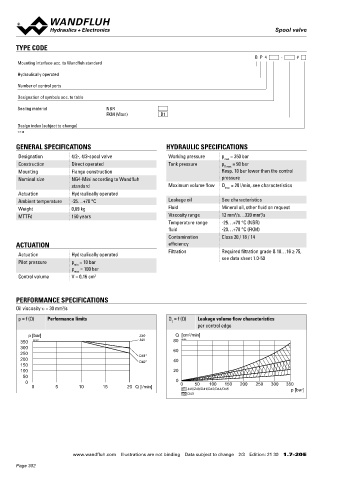
PERFORMANCE SPECIFICATIONS Technical explanations Data sheet 1.0-100
Oil viscosity u = 30 mm /s
2
Filtration Data sheet 1.0-50
p = f (Q) Performance limits Q = f (Q) Leakage volume flow characteristics
L
per control edge
3
p [bar] Z40 Q [cm /min] SEALING MATERIAL STANDARDS
350 K0097 J40 80 K0125 NBR or FKM (Viton) as standard, choice in the type code Mounting interface Wandfluh standard
300 60 Contamination ISO 4406
250 D41*
200 D42* 40 efficiency
150
100 20 INSTALLATION NOTES SURFACE TREATMENT
50
0 0 0 50 100 150 200 250 300 350 Mounting type Flange mounting ◆ The valve body is coated with a two component paint
0 5 10 15 20 Q [l/min] J40/Z40/D41/D42/D44/D45 p [bar] 3 fixing holes for ◆ The covers and the screws are zinc coated
D43 socket head screws M5 x 40
Mounting position Any, preferably horizontal
Tightening torque Fixing screws M = 5,2 Nm (screw
D
quality 8.8, zinc coated)
Note! The length of the fixing screw depends on the base
material of the connection element.
Wandfluh AG Postfach CH-3714 Frutigen
Tel. +41 33 672 72 72 Fax +41 33 672 72 12 sales@wandfluh.com
www.wandfluh.com Illustrations are not binding Data subject to change 2/3 Edition: 21 30 1.7-20 E www.wandfluh.com Illustrations are not binding Data subject to change 3/3 Edition: 21 30 1.7-20 E
Page 302