
Page 616 - Softbound_Edition_19_en
P. 616
Poppet valve
Poppet valve Poppet valve
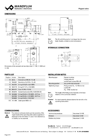
DIMENSIONS Solenoid operated poppet valve with inductive
switching position monitoring NG6
9.5 ◆ 2/2- or 3/2-way execution ISO 4401-03
110 5.5 MD= 5.2Nm ◆ Q = 40 l/min x II 2 G Ex db IIC T6, T4
max
t=45 (K9) ◆ p = 350 bar
max
t=47 (K10)
93.8 (K9) 114.5 (K10) 8
38 45 46
23
64 10 DESCRIPTION
12 17 18 10 18 70 40 60 Solenoid operated poppet valve according to data sheet 1.11-3143
MD=9Nm MD= 5.2Nm 177.4 (K9) , 179.4 (K10) AEXd.2060b
60 (K9) 8.1 with additional inductive switching position monitoring. The con-
62 (K10)
98.1 (K9) 64 15.3 Note! The K9 coil (K10 valve) is 1 mm larger than the valve tactless sensor transmits the poppet position to a step signal.
100.1 (K10)
162.1 (K9) , 164.1 (K10) AEXd22061a body. Usually, a distance plate is necessary.
177.4 (K9) , 179.4 (K10) AEXd32061a
K9 K10 TYPE CODE
HYDRAULIC CONNECTION
s8 A EXd 2 06 / - Z104 #
s8 s2.5 International standard interface ISO
s2.5 17.8
114 T Explosion proof execution
42 94 42
31 A B 21 32.5 2-Wege (Anschlüsse) 2 3
3-Wege (Anschlüsse)
22.5 24 P
45 47 21.5 2 switching positions
Dimensions of the solenoid coil see data sheet 1.1-183, 1.1-183S and 40.5 Nominal size 6
1.1-184
Normally closed Solenoid on A-side 1a
Normally open Solenoid on B-side 0b
PARTS LIST INSTALLATION NOTES Other type designation according to type code data sheet 1.11-3143
Position Article Description Mounting type Flange mounting Namur / monitoring
10 263.6... Solenoid coil MK.45 / 18 x 60 4 fixing holes for Design index (subject to change)
12 154.2201 Knurled nut Ex M18 x 1,5 x 30 socket head screws M5 x 45 1.11-3144
Mounting position Any, preferably horizontal
17 160.2251 O-ring ID 25,07 x 2,62 (NBR) Tightening torque Fixing screws M = 5,1 Nm (screw
18 160.2170 O-ring ID 17,17 x 1,78 (NBR) quality A4) D
40 058.4221 Cover 45 /45 x 17,5 K9 M = 9 Nm knurled nut GENERAL SPECIFICATIONS
D Namur-Sensor Specifications:
60 246.2516 Socket head screw M5 x 16 A4 DIN 912 Designation 2/2-, 3/2-way poppet valve
Note! The length of the fixing screw depends on the base
70 160.2093 O-ring ID 9,25 x 1,78 (NBR) „-25 °C to…” material of the connection element. Construction Direct operated Nominal voltage 8,2 VDC
160.7092 O-ring ID 9,25 x 1,78 (NBR) „-40 °C to…” Mounting Flange construction Operating voltage 7,7…9 VDC
160.6092 O-ring ID 9,25 x 1,78 (FKM) Nominal size NG6 according to ISO 4401-03 Current consumption damped max. 1 mA
Attention! For stack assembly please observe the remarks in the
110 111.1080 Cable gland M20 x 1,5 Actuation Switching solenoid Current consumption undamped min. 4 mA
operating instructions
Ambient temperature L9: -25…+40 °C Admissible series resistor R 550…1100 Ohm
v
L15: -25…+70 °C Switching frequency 1000 Hz
Weight 3,30 kg Protection class IP 68
MTTFd 150 years According to the connection
COMMISSIONING ACCESSORIES type, the protection class of the
Attention! The solenoid coil must only be put into operation, if the Technical explanations Data sheet 1.0-100 valve can be lower, see
requirements of the operating instructions supplied are data sheet 1.11-3143
observed to their full extent. In case of non-observance, Filtration Data sheet 1.0-50 Dimensions M12 x 1
no liability can be assumed. Relative duty factor Data sheet 1.1-430 Ambient temperature -25…70 °C
Fastening torque 15 Nm
Peak pressure 500 bar
Wandfluh AG Postfach CH-3714 Frutigen
Tel. +41 33 672 72 72 Fax +41 33 672 72 12 sales@wandfluh.com
www.wandfluh.com Illustrations are not binding Data subject to change 4/4 Edition: 21 18 1.11-3143S E www.wandfluh.com Illustrations are not binding Data subject to change 1/2 Edition: 21 05 1.11-3144 E
Page 616