Page 234 - Softbound_Edition_19_en
P. 234

Solenoid operated spool valve
                                                                                Solenoid operated spool valve                                                                                                Solenoid operated spool valve


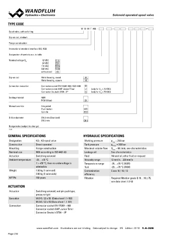
       TYPE CODE                                                                                                                   ELECTRICAL SPECIFICATIONS                            MANUAL OVERRIDE
                                                          W  W  M  F  A06  -     -     /        -           #                       Protection class   Connection execution D: IP65      ◆  Integrated (–) Actuation pin integrated in the armature tube.
       Spool valve, soft switching                                                                                                                     Connection execution J: IP66       Actuation by pressing the pin
                                                                                                                                                       Connection execution G: IP67 and IP69K  ◆  Push-button (HF1) Integrated in the knurled nut. Actuation by
       Slip-on coil, medium                                                                                                                                                               pressing the push-button
                                                                                                                                    Relative duty factor  100 % DF
       Flange construction                                                                                                          Switching frequency  Since switching is damped and slow,   ◆  Spindle (HS1) Integrated in the knurled nut. Actuation by turning
                                                                                                                                                                                          the spindle (continuously variable valve actuation)
                                                                                                                                                       switching frequency is of secondary
       International standard interface ISO, NG6                                                                                                                                        Attention!  The actuation of the manual override is possible up to a
                                                                                                                                                       importance.
                                                                                                                                                        7
       Designation of symbols acc. to table                                                                                         Service life time  10  (number of switching cycles,          tank pressure of:
                                                                                                                                                                                                 40 bar Integrated (–)
                                                                                                                                                       theoretically)                            40 bar Push-button (HF1)
       Nominal voltage U        12 VDC   G12                                                                                        Voltage tolerance  ± 10 % with regard to nominal voltage     100 bar Spindle (HS1)
                   N
                                24 VDC   G24
                              115 VAC   R115                                                                                        Standard nominal   12 VDC, 24VDC, 115 VAC, 230 VAC
                              230 VAC   R230                                                                                        voltage            AC = 50 to 60 Hz, rectifier integrated in
                              without coil   X5                                                                                                        the connector socket
       Slip-on coil           Metal housing, round          W                                                                      Note!    Other electrical specifications see data sheet 1.1-182
                              Metal housing, square          M                                                                              (slip-on coil W) and 1.1-181 (slip-on coil M)

       Connection execution   Connector socket EN 175301-803 / ISO 4400   D
                              Connector socket AMP Junior-Timer   J   (only for U  ≤ 75 VDC)
                                                                        N
                              Connector Deutsch DT04 - 2P    G   (only for U  ≤ 75 VDC)                                            STANDARDS                                            SEALING MATERIAL
                                                                        N
       Sealing material       NBR                                                                                                   Mounting interface  ISO 4401-03                     NBR or FKM (Viton) as standard, choice in the type code
                              FKM (Viton)                   D1                                                                      Solenoids           DIN VDE 0580

       Manual override        Integrated                                                                                            Connection execution D  EN 175301 – 803
                              Push-button                   HF1                                                                     Protection class    EN 60 529
                              Spindle                       HS1                                                                     Contamination efficiency ISO 4406

       Orifice diameter       Ø 0.3 mm (Standard)
                              Ø 0.5 mm                      Q0.5
       Design index (subject to change)
                                                                                                                                   SURFACE TREATMENT                                    COMMISSIONING
       1.4-32
                                                                                                                                    ◆  The valve body is painted with a two component paint
       GENERAL SPECIFICATIONS                              HYDRAULIC SPECIFICATIONS                                                 ◆  The screw plug, the slip-on coil and the armature tube are   Attention!   When commissioning, the valve must be vented under
       Designation        4/2-, 4/3-spool valve             Working pressure   p  = 350 bar                                           zinc-nickel coated                                         pressure (max. two rotations of screw E).
                                                                                max
       Construction       Direct operated                   Tank pressure      p   = 200 bar
                                                                                T max
       Mounting           Flange construction               Maximum volume flow  Q  = 60 l/min, see characteristics
                                                                                max
       Nominal size       NG6 according to ISO 4401-03      Leakage oil        See characteristics
       Actuation          Switching solenoid                Fluid              Mineral oil, other fluid on request
       Ambient temperature  -25…+70 °C                      Viscosity range    12 mm /s…320 mm /s                                  ACCESSORIES                                          INSTALLATION NOTES
                                                                                   2
                                                                                            2
                          if > +50 °C, then no undervoltage is   Temperature range   -25…+70 °C (NBR)                               Mating connector grey (A)    Article no. 219.2001    Mounting type      Flange mounting
                          admissible                        fluid              -20…+70 °C (FKM)                                     Mating connector black (B)   Article no. 219.2002                       4 fixing holes for
       Weight             1.50 kg (1 solenoid)              Contamination      Class 18 / 16 / 13                                   Mounting screws              Data sheet 1.0-60                          socket head screws M5 x 50
                          2.00 kg (2 solenoids)             efficiency                                                                                                                   Mounting position  Any, preferably horizontal
       MTTFd              150 years                         Filtration         Required filtration grade ß 10…16 ≥ 75,              Threaded subplates           Data sheet 2.9-30       Tightening torque  Fixing screws M  = 5,2 Nm (screw
                                                                                                                                                                                                                       D
                                                                               see data sheet 1.0-50                                Multi-station subplates      Data sheet 2.9-60                          quality 8.8, zinc coated)
                                                                                                                                    Horizontal mounting blocks   Data sheet 2.9-100                         M  = 5 Nm knurled nut
       ACTUATION                                                                                                                                                                                             D
                                                                                                                                    Technical explanations       Data sheet 1.0-100
       Actuation          Switching solenoid, wet pin push type,                                                                    Filtration                   Data sheet 1.0-50      Note!    The length of the fixing screw depends on the base
                                                                                                                                                                                                 material of the connection element.
                          pressure tight                                                                                            Relative duty factor         Data sheet 1.1-430
       Execution          W.E45 / 23 x 50  (Data sheet 1.1-182)
                          M.S45 / 23 x 50 (Data sheet 1.1-181)
       Connection         Connector socket EN 175301 – 803
                          Connector socket AMP Junior-Timer
                          Connector Deutsch DT04 – 2P


                           www.wandfluh.com  Illustrations are not binding  Data subject to change  2/5  Edition: 22 10  1.4-32 E                      www.wandfluh.com  Illustrations are not binding  Data subject to change  3/5  Edition: 22 10  1.4-32 E
       Page 234
   229   230   231   232   233   234   235   236   237   238   239