
Page 74 - Softbound_Edition_19_en
P. 74
Solenoid
Solenoids Solenoids
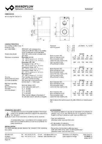
DIMENSIONS
20x1,5 / NPT 1/2“ Digital amplifier electronics to MKY...M248
without amplifier electronics With amplifier electronics and with analogue interface
• Electronics integrated in solenoid housing
M • For proportional or switching valves
93,3 • Screw terminals for simple assembly
42
• 1 analogue input
• 1 digital input
22 18,2
Ø • Adjustable with push-buttons and display directly on the device or via PC
Ø
22,5
20°
1,4 ELECTRICAL SPECIFICATIONS
60 45 Supply voltage G12: 12 V +10 %, G24: 24 V +10 % G24/L9 Adjustable I …510 m A
min
Residual ripple < +/-5 % Factory setting 600 mA
CHARACTERISTICS Fuse low G12/L9 Adjustable I …685 m A
min
Coil winding isolation class H Standard P = 6 W with M272 P = 3,8 W No-load current approx. 20 mA Factory setting 610 mA
N
R
Protection class nominal powers P = 9 W Max. current Dither Frequency adjustable 4…500 Hz
N
acc. to EN 60529 IP65/66/67, with corresponding P = 15 W consumption No-load current + limiting Factory setting 80 Hz
N
cable gland with front side O-ring sealing P = 21 W current of the solenoid Level adjustable 0…400 mA
N
to the housing and correct installation Analogue input 1 input non-differential Factory setting 150 mA
Relative duty factor 100 % DF, combined with armature tube 12 VDC Voltage / current (switchable by means of parameter) Temperature drift <1 % at ∆T = 40 °C
and valve Nominal power (W) 6 9 12 15 21 0...+/- 10V or 0/4...20mA Digital inputs 1 input high-active, no pull-up/down
Reference temperature Execution L6 / L9: Nominal resistance (Ω) 24,75 16,5 13,5 9,9 7,1 Resolution 10-Bit Switching threshold high 6...32 VDC
-25…+40 °C (operation as T1…T6/T80 °C) Recommended rated 1000 1600 2000 2500 4000 Input resistance Voltage input >100 kΩ Switching threshold low 0…1 VDC
-25…+90 °C (operation as T1…T4/T130 °C) current for fuse inserts (mA) (Input current < 5 mA) Usable as frequency input
Execution L15 / L12: Limiting current (mA) 400 610 720 960 1230 Load for current input = 124 Ω (frequency 5...5000 Hz) and as PWM input
Temperature range „-25° to...“ (Proportional function) Stabilised output 5 VDC (automatic frequency recognition)
-25…+70 °C (operation as T1…T4/T130 °C) voltage max. load 20 mA USB interface Via digital input
Temperature range „-40° to ...“ 24 VDC Solenoid current: Requires the Wandfluh USB adapter PD2
-40…+70 °C (operation as T1…T4/T130 °C) Nominal power (W) 6 9 12 15 21 • Minimal current I Adjustable 0…I max mA EMC
min
Temperature range „-60° to ...“ Nominal resistance (Ω) 98,5 64 49,2 38,5 27,5 Factory setting 30 mA Immunity EN 61 000-6-2
-60…+70 °C (operation as T1…T4/T130 °C) Recommended rated 400 800 800 1250 2000 • Maximal current I max G24/L15 Adjustable I …510 m A Emission EN 61 000-6-4
min
Execution L 21: current for fuse inserts (mA) Factory setting 450 mA
-25…+60 °C (operation as T1…T4/T130 °C) Limiting current (mA) 200 300 370 450 600 G12/L15 Adjustable I …1020 m A
min
Housing Steel housing, zinc-/nickel-coated (Proportional function) Factory setting 960 mA
Relative humidity factor max. 95 % (not dew-forming)
Corrosion protection Salt spray test in accordance with 115 VAC
EN ISO 9227 > = 1000 hours Nominal power (W) 6 9 12 15 21 DIMENSIONS
Maximum operating Nominal resistance (Ω) 1840 1180 869 700 500 with amplifier electronics
voltage Nominal voltage +10 % Recommended rated 100 200 200 315 400
Nominal frequency in acc. with name plate ±2 % current for fuse inserts (mA) X1
Standard U = 12 VDC 1 2 3 4 5
N
nominal voltages U = 24 VDC 230 VAC X1
N
U = 115 VAC Nominal power (W) 6 9 12 15 21 1 2 3 4 5
N
U = 230 VAC Nominal resistance (Ω) 7280 4750 3370 2850 2050
N
Other nominal voltages in the ranges of Recommended rated 100 100 100 160 200
12–230 VDC and 24–230 VAC on request current for fuse inserts (mA) M20x1.5/NPT 1/2"
M272 reduces the nominal power (P ) after 500ms to a reduced power 124
N
(P ) up down enter
R
42
22
Ø Ø18.2
OPERATION SECURITY ACCESSORIES 20° 22.5 45
The solenoid coil must only be put into operation, if the require- – The operating instructions incl. the EC declaration of conformity for 1.4
ments of the operating instructions supplied are observed to solenoid coils of the type MKY45/18 x 60 is supplied in German,
their full extent. English and French (download under www.wandfluh.com) 60 45
In case of non-observance, no liability can be assumed. CONNECTOR ASSIGNMENT (X1) GENERAL SPECIFICATIONS
– Type test certifications 1 = + VCC
A corresponding fuse in accordance with its design current (download under www.wandfluh.com) 2 = Command value Execution Electronics board built-in directly
has to be connected in series as short-circuit protection for 3 = Dig Inp in solenoid housing
every solenoid coil. – EC-declaration of conformity 4 = Stab out Connections
(download under www.wandfluh.com) 5 = GND Screw terminal 5-pole, max 1,0 mm 2
INSTALLATION USB interface via connection «Digital Input»
For stack assembly please observe the remarks in the operating – Recognition of production quality assurance requires an additional Wandfluh
instructions. QAN: SEV ATEX 4130, QAR: CH/SEV/QAR16.0001 adapter PD2
(download under www.wandfluh.com)
Wandfluh AG Tel. +41 33 672 72 72 E-mail: sales@wandfluh.com Illustrations not obligatory Data sheet no. Wandfluh AG Tel. +41 33 672 72 72 E-mail: sales@wandfluh.com Illustrations not obligatory Data sheet no.
Postfach Fax +41 33 672 72 12 Internet: www.wandfluh.com Data subject to change 1.1-183E 2/5 Postfach Fax +41 33 672 72 12 Internet: www.wandfluh.com Data subject to change 1.1-183E 3/5
CH-3714 Frutigen Edition 22 11 CH-3714 Frutigen Edition 22 11
Page 74