
Page 47 - Softbound_Edition_19_en
P. 47
Solenoids Solenoids
Solenoid
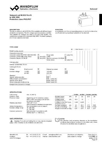
TYPE LISTE / DIMENSIONS / GENERAL SPECIFICATIONS Solenoid coil M.S35 /16 x 53
to VDE 0580
Protection class IP65 / IP67
47.5
47.5
Ø 16
Ø 16
47.5 Execution: W D E37/16 x 40-...
Ø 16 • 3-poles 2 P+E
• Protection class IP 65
• • With corresponding mating connector
• • (not included in delivery) DESCRIPTION FUNCTION
40 The slip-on solenoid coil M.S35/16 x 53 is available with different types In combination with the corresponding armature tube the function of an
40 • • and professional assembly.
40 of electric connections. The AC voltage type incorporates a rectifier. on-off solenoid or proportional solenoid will be obtained.
The available AC voltages are listed in the type code section. The
construction corresponds to standard VDE 0580. The steel housing is
Ø 37 zinc-/nickel-coated as standard.
Ø 37
Ø 37
TYPE CODE
47.5
47.5 M S35 / 16 x 53 - - #
47.5 Execution: W J E37/16 x 40-… Metal housing, square
• 2-poles 2P Connection execution
• only for U ≤ 75 VDC
N
• Protection class IP 66 Connector socket EN175301-803 / ISO 4400 D Flying leads L (only DC)
40 • • With corresponding mating connector Connector socket AMP Junior-Timer J (only DC) Cable K
40 Connector Deutsch DT04-2P G (only DC) Bayonet connector VG 95234 B
40 • • (not included in delivery) Screw clamp X (only DC)
• • and professional assembly.
Coil execution
Internal coil diameter 16 mm
Coil length 53 mm
Voltage Direct current G Alternating current R
Nominal voltage 12 VDC 12 115 VAC 115
24 VDC 24 230 VAC 230
55.3 Execution: W G E37/16 x 40-…
55.3 • 2-poles 2P Standard
55.3 • only for U ≤ 75 VDC Special cable execution M28
N
• Protection class IP 67 and 69 K With pressure compensation M35 (only DC)
• • With corresponding mating connector Special screw clamp M209 (only DC)
40 • • (not included in delivery) Screw clamp and electric wiring M222 (only DC)
40 • • and professional assembly. Design-Index (Subject to change)
40
SPECIFICATIONS
Technical explanation see data sheet 1.1-400 and 1.1-410 Coil winding min. H (180 °C) 12 VDC 24 VDC 115 VAC 230 VAC
insulation class Nominal power (W) 23 22 25,5 28
Protection class depending on the connector version (Switching function)
IP65 or IP67 according to EN 60 529 Limiting power (W) 15,5 15 – –
(if correctly mounted) (Proportional function)
Relative duty factor 100 % DF / 5 min Limiting current (50 °C) (A) 1,285 0,625 – –
when mounted on armature tube and valve (Proportional function) (Ω) 6,3 26,1 413 1500
Nominal resistance
Ambient temperature See temperature curve on page 4 Number of windings (–) 815 1656 5 930 12 000
Nominal voltage range 10 – 250 VDC Weight of solenoid coil (kg) 0,37 0,37 0,37 0,37
24 – 250 VAC
Corrosion protection Salt spray test in accordance with
EN ISO 9227 > = 1000 hours
SAFE OPERATION NOTE!
Caution: To avoid overheating the coil may only be energised The effective heat emissions depends on the installation
when mounted on an armature tube and valve. conditions (heat emission surface, air circulation, etc.), these
influence the described area of application.
Wandfluh AG Tel. +41 33 672 72 72 E-mail: sales@wandfluh.com Illustrations not obligatory Data sheet no. Wandfluh AG Tel. +41 33 672 72 72 E-mail: sales@wandfluh.com Illustrations not obligatory Data sheet no.
Postfach Fax +41 33 672 72 12 Internet: www.wandfluh.com Data subject to change 1.1-169E 2/2 Postfach Fax +41 33 672 72 12 Internet: www.wandfluh.com Data subject to change 1.1-170E 1/4
CH-3714 Frutigen Edition 21 30 CH-3714 Frutigen Edition 19 30
Page 47