
Page 216 - Softbound_Edition_19_en
P. 216
Solenoid operated spool valve
Solenoid operated spool valve Solenoid operated spool valve
DIMENSIONS Solenoid operated spool valve
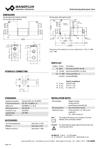
4/3-way spool valve (spring centring) 4/2-way spool valve (spring reset) Flange construction NG6
4/2-way spool valve (impulse) 9.5 ISO 4401-03
110 ◆ 4/2-way impulse execution, detented
5.2
◆ 4/3-way with spring centered mid position x II 2 G Ex db IIC T6, T4
t=45 (K9) MD= 5.2Nm
t=47 (K10) 8 ◆ 4/2-way with spring reset
96.8 (K9) 116.2 (K10) ◆ Q = 80 l/min
max
p = 350 bar
◆
max
41 49
26
DESCRIPTION
10 Spool valve according to data sheet 1.3-34 with additional inductive
12
258 (K9) MD=9Nm 17 18 10 18 70 40 MD=50Nm
262 (K10)
60 (K9) 5 switching position monitoring. The contactless sensor transmits the
62 (K10)
K9 K10 95 (K9) 68 12.6 spool position to a step signal.
97 (K10)
s8 s8 175.6 (K9)
177.6 (K10)
s2.5
s2.5
Dimensions of the solenoid coil, refer to data sheet 1.1-183, 1.1-183S TYPE CODE
42 94 114 and 1.1-184 WD Y F A06 - - #
42 Spool valve, direct operated
22.5 Explosion proof execution, Ex d
24
45 Flange construction
47 PARTS LIST
International standard interface ISO NG6
Position Article Description
10 263.6... Solenoid coil MK.45 / 18 x 60 Other type designation according to type code data sheet 1.3-34
HYDRAULIC CONNECTION 12 154.220. Knurled nut Ex M18 x 1,5 x 30-K.. Namur / Monitoring single Z104
110 111.1080 Cable gland M20 x 1,5 double Z72 / 104 (only 4/2-way spool valves)
17.8 - 251.2218 Seal kit WDYFA06 Design index (subject to change)
T 1.3-36
A B Seal kit consisting of
31 21 32.5 17 O-ring ID 25,07 x 2,62
18 O-ring ID 17,17 x 1,78 GENERAL SPECIFICATIONS Namur-Sensor Specifications:
P
70 O-ring ID 9,25 x 1,78 Designation 4/2-, 4/3-spool valve
21.5 Construction Direct operated Nominal voltage 8,2 VDC
40.5 Operating voltage 7,7…9 VDC
Mounting Flange construction Current consumption damped max. 1 mA
Nominal size NG6 according to ISO 4401-03 Current consumption undamped min. 4 mA
Actuation Switching solenoid Admissible series resistor R 550…1100 Ohm
STANDARDS INSTALLATION NOTES v
Ambient temperature L9: -25…+40 °C Switching frequency 1000 Hz
Explosion protection Directive 2014 / 34 / EU (ATEX) Mounting type Flange mounting L15: -25…+70 °C Protection class IP 68
Flameproof enclosure EN / IEC / UL 60079-1, 31 4 fixing holes for Weight 0,5 kg single flange According to the connection
Cable entry EN 60079-0, 1, 7, 15, 31 socket head screws M5 x 50 1,0 kg double flange type, the protection class of the
Mounting interface ISO 4401-03 Mounting position Any, preferably horizontal MTTFd 150 years valve can be lower, see
Protection class EN 60 529 Tightening torque Fixing screws M = 5,1 Nm (screw data sheet 1.2-59
D
Contamination ISO 4406 quality A4) Dimensions M12 x 1
efficiency M = 9 Nm knurled nut Ambient temperature -25…70 °C
D
Fastening torque 15 Nm
Note! The length of the fixing screw depends on the base Peak pressure 500 bar
ACCESSORIES material of the connection element.
Technical explanations Data sheet 1.0-100 SURFACE TREATMENT ACCESSORIES
Filtration Data sheet 1.0-50 Attention! For stack assembly please observe the remarks in the ◆ The valve body is painted with a two component paint
operating instructions Mating connector (plug female, confectionable)
Relative duty factor Data sheet 1.1-430 ◆ All the other parts are zinc-nickel coated straight, screw terminal Article no. 219.2978
angled, screw terminal Article no. 219.3003
Wandfluh AG Postfach CH-3714 Frutigen
Tel. +41 33 672 72 72 Fax +41 33 672 72 12 sales@wandfluh.com
www.wandfluh.com Illustrations are not binding Data subject to change 4/4 Edition: 23 12 1.3-34S E www.wandfluh.com Illustrations are not binding Data subject to change 1/2 Edition: 21 07 1.3-36 E
Page 216