
Page 214 - Softbound_Edition_19_en
P. 214
Solenoid operated spool valve
Solenoid operated spool valve Solenoid operated spool valve
TYPE CODE ELECTRICAL SPECIFICATIONS SURFACE TREATMENT
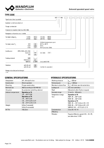
WD Y F A06 - - / / - # Protection class IP65 / 66 / 67 -The valve body, the cover and the socket head screws are made of
Spool valve direct operated Relative duty factor 100 % DF stainless steel
-The slip-on coil and the armature tube are zinc nickel coated
Explosion proof execution Ex d Switching frequency 12'000 / h Optionally K10:
Voltage tolerance ± 10 % with regard to nominal voltage -The coil is made of stainless steel
Flange construction Standard nominal 12 VDC, 24VDC, 115 VAC, 230 VAC
voltage AC = 50 to 60 Hz ± 2 %, with built-in
International standard interface ISO, NG6 SEALING MATERIAL
two-way rectifier
Designation of symbols acc. to table Standard nominal 9 W, 15 W, 17 W NBR or FKM (Viton) as standard, choice in the type code
power
Nominal voltage U N 12 VDC G12 115 VAC R115 INBETRIEBNAHME
24 VDC G24 230 VAC R230 Temperature class Nominal power 9 W: T1…T6 The solenoid coil must only be put into operation, if the
Nominal power 15 W / 17 W: T1…T4 Attention!
Ambient temperature up to: Other electrical specifications see data sheet 1.1-183, requirements of the operating instructions supplied are
Nominal power P N 9 W L9 40 °C or 90 °C Note! observed to their full extent. In case of non-observance,
15 W L15 70 °C 1.1-183S and 1.1-184 no liability can be assumed.
17 W L17 70 °C (only UL / CSA)
Certification ATEX, IECEx, CCC, EAC PERFORMANCE SPECIFICATIONS
Australia AU UL / CSA UL 2
MA MA Oil viscosity u = 30 mm /s
p = f (Q) Performance limits p = f (Q) Performance limits L9
Sealing material NBR Measured with nominal voltage -10% Measured with nominal voltage -10%
FKM (Viton) D1
NBR 872 y-Z604 (only with 15 W) at 50 °C (steady-state temperature) at 40 °C (steady-state temperature)
Execution L9 90 °C on request
Stainless with K8 coil K9
with K9 coil K10 (not for UL execution) p [bar] AB1 / AB2 ADB ACB AB3/BEA p [bar] ADB ACB AB3
350 K4196 350 K4197
Design index (subject to change) 300 300
1.3-34S 250 250 AB1 / AB2
200 200
150 150
GENERAL SPECIFICATIONS HYDRAULIC SPECIFICATIONS 100 100
50 50
Designation 4/2-, 4/3-spool valve Working pressure p = 350 bar
max 0 Q [l/min] 0 Q [l/min]
Construction Direct operated Tank pressure p = 200 bar 0 10 20 30 40 50 0 5 10 15 20 25 30
T max
Mounting Flange construction Maximum volume flow Q = 50 l/min, see characteristics
max
Nominal size NG6 according to ISO 4401-03 Leakage oil See characteristics
Actuation Ex-protection switching solenoid Fluid Mineral oil, other fluid on request Δp = f (Q) Pressure drop volume flow characteristic Volume flow direction
Ambient temperature Operation as T6 Viscosity range 12 mm /s…320 mm /s per control edge Symbol P-A P-B P-T A-T B-T
2
2
-25…+40 °C (L9) Temperature range Operation as T6 p [bar] AB1 / AB3 2 2 - 3 3
Operation as T4 fluid NBR -25…+40 °C (L9) 20 K4291 4 ACB 1 1 - 2 2
-25…+90 °C (L9) FKM -20…+40 °C (L9) 18 3 ADB 1 1 - 1 1
16
-25…+70 °C (L15 / L17) Operation as T4 14 2 1
12
-40…+70 °C (L15 / L17) NBR -25…+70 °C (L9 or L15 / L17) 10 BEA 1 1 4 2 2
Weight 2,8 kg (1 solenoid) FKM -20…+70 °C (L9 or L15 / L17) 8 6
4,6 kg (2 solenoids) NBR 872 -40…+70 °C (L15 / L17) 4 2
L
MTTFd 150 years Contamination Class 20 / 18 / 14 0 0 5 10 15 20 25 30 35 40 45 50 Q [l/min] Q = f (Q) Leakage volume flow characteristics
P → T
efficiency
3
Filtration Required filtration grade ß 10…16 ≥ 75, Q [cm /min]
L
see data sheet 1.0-50 300 K4199
250
Note! With the L15 / L17 execution for ambient temperatures BEA
up to 70 °C, the performance specifications have been 200
evaluated with an ambient temperature of 50 °C 150 AB1 / AB2
100 AB3
Attention! For valves for the temperature ranges „-40 °C to…” 50 ACB / ADB
(Z604) the leakage volume flow can be up to eight times 0 p [bar]
higher. 0 50 100 150 200 250 300 350
www.wandfluh.com Illustrations are not binding Data subject to change 2/4 Edition: 23 12 1.3-34S E www.wandfluh.com Illustrations are not binding Data subject to change 3/4 Edition: 23 12 1.3-34S E
Page 214