Page 211 - Softbound_Edition_19_en
P. 211

Solenoid operated spool valve
                                                                                     Solenoid operated spool valve


            DIMENSIONS
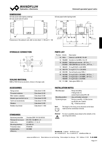
            4/3-way spool valve (spring centring)                4/2-way spool valve (spring reset)
            4/2-way spool valve (impulse)
                                                                       110
                                                                                                      MD=5.2Nm
                                                                                                 9.5
                                                                                                 5.5        8
                                                                    94.3   15
                                                                    MD=5.5Nm                                  49
                                                                      23.5                                  41

                 10
                                                                       12
                                  245.9                             MD=9Nm  17  18 10  18         70     40
            Dimensions of the solenoid coil, refer to data sheet 1.1-183 and 1.1-184                       MD=50Nm
                                                                                    60      5
                                                                                  89             68       12.6
                                                                                         169.6


            HYDRAULIC CONNECTION                                 PARTS LIST
                                                                  Position Article  Description
                                      17.8
                                                                       10 263.6...  Solenoid coil MK.45 / 18 x 60
                                 T
                                                                       12 154.2603  Knurled nut Ex M18 x 1,5 x 18
                              A       B                                15 253.8001  HB6 Manual override „-25 °C to…”
                          31                     21    32.5
                                                                          253.8025  HB6-Z604 Manual override „-40 °C to…”
                                 P                                     17 160.2251  O-ring ID 25,07 x 2,62 (NBR)
                               21.5                                    18 160.2170  O-ring ID 17,17 x 1,78 (NBR)
                                 40.5
                                                                       40 239.2205  Socket head screw M20 x 1
                                                                       70 160.2093  O-ring ID 9,25 x 1,78 (NBR) „-25 °C to…”
                                                                          160.7092  O-ring ID 9,25 x 1,78 (NBR) „-40 °C to…”
            SEALING MATERIAL                                              160.6092  O-ring ID 9,25 x 1,78 (FKM)
            NBR or FKM (Viton) as standard, choice in the type code   110 111.1080  Cable gland M20 x 1,5


            ACCESSORIES                                          INSTALLATION NOTES
             Fixing screws               Data sheet 1.0-60        Mounting type      Flange mounting
             Threaded subplates          Data sheet 2.9-30                           4 fixing holes for
             Multi-station subplates     Data sheet 2.9-60                           socket head screws M5 x 50
                                                                  Mounting position  Any, preferably horizontal
             Module type manifold blocks  Data sheet 2.9-100      Tightening torque  Fixing screws M  = 5,2 Nm (screw
                                                                                                D
             Technical explanations      Data sheet 1.0-100                          quality 8.8, zinc coated)
             Filtration                  Data sheet 1.0-50                           M  = 9 Nm knurled nut
                                                                                      D
             Relative duty factor        Data sheet 1.1-430
                                                                 Note!    The length of the fixing screw depends on the base
                                                                          material of the connection element.


            STANDARDS                                            Attention!  For stack assembly please observe the remarks in the
                                                                          operating instructions
             Explosion protection  Directive 2014 / 34 / EU (ATEX)
             Flameproof enclosure  EN / IEC / UL 60079-1, 31
             Cable entry        EN 60079-0, 1, 7, 15, 31
             Mounting interface  ISO 4401-03
             Protection class   EN 60 529
             Contamination      ISO 4406
             efficiency                                          Wandfluh AG  Postfach  CH-3714 Frutigen
                                                                 Tel. +41 33 672 72 72  Fax +41 33 672 72 12  sales@wandfluh.com

                                www.wandfluh.com  Illustrations are not binding  Data subject to change  5/5  Edition: 21 05  1.3-34 E
                                                                                                            Page 211
   206   207   208   209   210   211   212   213   214   215   216