
Page 202 - Softbound_Edition_19_en
P. 202
Solenoid operated spool valve
Solenoid operated spool valve
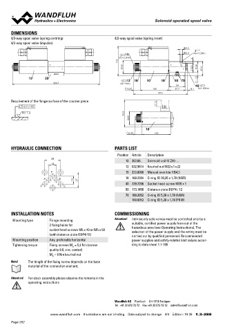
DIMENSIONS
4/3-way spool valve (spring centring) 4/2-way spool valve (spring reset)
4/2-way spool valve (impulse)
9.5
15 5.2 MD= 5.2Nm
102 MD=5.5Nm 6
45 38
32 49.5
10 50 12 18 10 18 50 70 11.5
304.7 MD=9Nm 54
23.8 100 57.2 8.1 40 MD=50Nm
189.1
Requirement of the flange surface of the counter piece
0.01/100
92.8 45
Ra 1.6
10
23.8 100
HYDRAULIC CONNECTION PARTS LIST
Position Article Description
28 10 263.66.. Solenoid coil M.Z45-...
14
12 032.9614 Knurled nut M22 x 1 x 22
P 15 253.8000 Manual override HB4,5
A B 18 160.2204 O-ring ID 20,35 x 1,78 (NBR)
14 27
T T0 40 239.2206 Socket head screw M20 x 1
50 173.1450 Distance plate BDP4 / 12
70 160.2052 O-ring ID 5,28 x 1,78 (NBR)
160.6052 O-ring ID 5,28 x 1,78 (FKM)
INSTALLATION NOTES COMMISSIONING
Mounting type Flange mounting Attention! Intrinsically safe valves must be controlled only by a
3 fixing holes for suitable, certified power supply from out of the
hazardous area (see Operating Instructions). The
socket head screws M5 x 40 or M5 x 50 selection of the power supply and the wiring must be
(with distance plate BDP4/12) carried out by qualified personnel. Recommended
Mounting position Any, preferably horizontal power supplies and safety-related limit values accor-
Tightening torque Fixing screws M = 5,2 Nm (screw ding to data sheet 1.1-185
D
quality 8.8, zinc coated)
M = 9 Nm knurled nut
D
Note! The length of the fixing screw depends on the base
material of the connection element.
Attention! For stack assembly please observe the remarks in the
operating instructions
Wandfluh AG Postfach CH-3714 Frutigen
Tel. +41 33 672 72 72 Fax +41 33 672 72 12 sales@wandfluh.com
www.wandfluh.com Illustrations are not binding Data subject to change 4/4 Edition: 19 26 1.3-28 E
Page 202