Page 205 - Softbound_Edition_19_en
P. 205

Solenoid operated spool valve
                                                                                     Solenoid operated spool valve


            ELECTRICAL SPECIFICATIONS                            MANUAL OVERRIDE
             Protection class   IP67                             HB6-Z591 for „-60…+70 °C”
             Relative duty factor  100 % DF
             Switching frequency  12'000 / h                     SURFACE TREATMENT
             Voltage tolerance  ± 10 % with regard to nominal voltage  ◆  The valve body is made of stainless steel
             Standard nominal   12 VDC, 24VDC, 115 VAC, 230 VAC   ◆  The armature tube and the plug screw are zinc-nickel coated
             voltage            AC = 50 to 60 Hz ± 2 %, with built-in
                                two-way rectifier
             Standard nominal   15 W
             power                                               COMMISSIONING
             Temperature class  Nominal power 15 W: T1…T4        Attention!  The solenoid coil must only be put into operation, if the
                                                                            requirements of the operating instructions supplied are
            Note!    Other electrical specifications see data sheet 1.1-183
                                                                          observed to their full extent. In case of non-observance,
                                                                          no liability can be assumed.


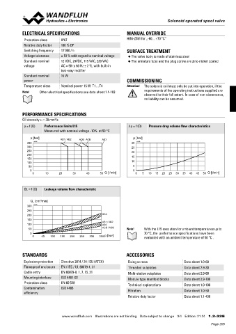
            PERFORMANCE SPECIFICATIONS
                             2
            Oil viscosity u = 30 mm /s
             p = f (Q)  Performance limits L15                    ∆p = f (Q)  Pressure drop volume flow characteristics
                       Measured with nominal voltage -10%  at 50 °C

                p [bar]         AB1 / AB2  ADB ACB   AB3            p [bar]
               350  K4196                                          30  K4198
               300                                                 25
               250                                                 20
               200                                                 15
               150
               100                                                 10
               50                                                   5
                0                                                   0
                 0      10     20     30     40    50  Q [l/min]     0   5  10  15  20  25  30  35  40  45  50  Q [l/min]


             QL = f (Q)  Leakage volume flow characteristic


                Q  [cm /min]
                     3
                  L
               300  K4199
               250
               200                                   BEA
               150                                   AB1 / AB2
               100                                   AB3
               50                                    ACB / ADB   Note!    With the L15 execution for ambient temperatures up to
                0                                                         70 °C, the  performance specifications have been
                 0    50  100  150  200  250  300  350  p [bar]           evaluated with an ambient temperature of 50 °C .


            STANDARDS                                            ACCESSORIES

             Explosion protection  Directive 2014 / 34 / EU (ATEX)  Fixing screws             Data sheet 1.0-60
             Flameproof enclosure  EN / IEC / UL 60079-1, 31      Threaded subplates          Data sheet 2.9-30
             Cable entry        EN 60079-0, 1, 7, 15, 31          Multi-station subplates     Data sheet 2.9-60
             Mounting interface  ISO 4401-03                      Module type manifold blocks  Data sheet 2.9-100
             Protection class   EN 60 529                         Technical explanations      Data sheet 1.0-100
             Contamination      ISO 4406
             efficiency                                           Filtration                  Data sheet 1.0-50
                                                                  Relative duty factor        Data sheet 1.1-430


                                www.wandfluh.com  Illustrations are not binding  Data subject to change  3/4  Edition: 21 24  1.3-33 E
                                                                                                            Page 205
   200   201   202   203   204   205   206   207   208   209   210