Page 210 - Softbound_Edition_19_en
P. 210

Solenoid operated spool valve
                                                                                Solenoid operated spool valve                                                                                                Solenoid operated spool valve


       PERFORMANCE SPECIFICATIONS                                                                                                  DIMENSIONS
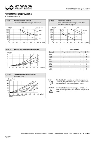
       Oil viscosity u = 30 mm /s                                                                                                  4/3-way spool valve (spring centring)                4/2-way spool valve (spring reset)
                       2
                                                                                                                                   4/2-way spool valve (impulse)
       p = f (Q)  Performance limits L15 / L17              p = f (Q)  Performance limits L9                                                                                                  110
                  Measured with nominal voltage -10% at 50 °C         Measured with nominal voltage -10% at 40 °C                                                                                                       9.5   MD=5.2Nm
                                                                      Execution L9 90 °C on request                                                                                                                     5.5        8
           p [bar]         AFB              AB1 / AB3 / ACB     p [bar]       BEA             AGB                                                                                          94.3   15
         350  K4105                                          350  K4106                                                                                                                    MD=5.5Nm
         300                                    AGB          300                                     AB1/AB3                                                                                                                       41    49
         250                                                 250                   AFB               ACB                                                                                     23.5
         200                                    ADB          200
         150                                                 150                                                                         10              245.9                                12  17   18 10  18         70     40
         100                                                 100                            ADB                                                                                            MD=9Nm                                 MD=50Nm
          50                                    BEA           50                                                                   Dimensions of the solenoid coil, refer to data sheet 1.1-183 and 1.1-184      60    5
           0                                                   0
            0   10  20  30   40  50  60  70   80  Q [l/min]      0   10  20  30  40   50  60  70  80  Q [l/min]                                                                                          89             68       12.6
                                                                                                                                                                                                                169.6

       Δp = f (Q)  Pressure drop volume flow characteristic                           Flow direction                               HYDRAULIC CONNECTION                                 PARTS LIST
          ∆p [bar]                                          Symbol         P - A  P - B  P - T   A - T  B - T
         30  K0171                        5                 AB1              2      2      -      1      1                                                   17.8                        Position Article  Description
         25                                    1            AB3              2      2      -      1      1                                                                                    10 263.6...  Solenoid coil MK.45 / 18 x 60
         20                                    2                                                                                                        T                                     12 154.2603  Knurled nut Ex M18 x 1,5 x 18
         15                                    3            ACB              2      2      -      1      1                                           A       B                                15 253.8001  HB6 Manual override „-25 °C to…”
         10                                    4            ADB              2      2      -      3      3                                       31                     21    32.5               253.8025  HB6-Z604 Manual override „-40 °C to…”
          5                                                 BEA              2      2      5      2      2                                              P                                     17 160.2251  O-ring ID 25,07 x 2,62 (NBR)
          0                                                 AFB              4      4      -      3      3
            0  10   20  30  40  50   60  70  80  Q [l/min]                                                                                            21.5                                    18 160.2170  O-ring ID 17,17 x 1,78 (NBR)
                                                            AGB              4      4      -      1      1                                              40.5
                                                                                                                                                                                              40 239.2205  Socket head screw M20 x 1
                                                                                                                                                                                              70 160.2093  O-ring ID 9,25 x 1,78 (NBR) „-25 °C to…”
       Q  = f (Q)  Leakage volume flow characteristics                                                                                                                                           160.7092  O-ring ID 9,25 x 1,78 (NBR) „-40 °C to…”
         L
                  per control edge                                                                                                                                                               160.6092  O-ring ID 9,25 x 1,78 (FKM)
                                                                                                                                   SEALING MATERIAL
           Q [cm /min]                                              With the L15 / L17 execution for ambient temperatures          NBR or FKM (Viton) as standard, choice in the type code   110 111.1080  Cable gland M20 x 1,5
               3
         150  K0232_3                                      Note!
                                                                    up to 70 °C, the  performance specifications have been
         120                                                        evaluated with an ambient temperature of 50 °C
          90                                                                                                                       ACCESSORIES                                          INSTALLATION NOTES
          60                                               Attention!  For valves for the temperature ranges „-40 °C to…”           Fixing screws                Data sheet 1.0-60       Mounting type      Flange mounting
                                                                    (Z604) the leakage volume flow can be up to eight times
          30                                                                                                                        Threaded subplates           Data sheet 2.9-30                          4 fixing holes for
                                                                    higher.
           0                                                                                                                        Multi-station subplates      Data sheet 2.9-60                          socket head screws M5 x 50
            0    50  100  150  200  250  300  350 p [bar]                                                                                                                                Mounting position  Any, preferably horizontal
               AB3/AB1/ACB/ADB/AFB/AGB                                                                                              Module type manifold blocks  Data sheet 2.9-100
               BEA                                                                                                                                                                       Tightening torque  Fixing screws M  = 5,2 Nm (screw
                                                                                                                                                                                                                       D
                                                                                                                                    Technical explanations       Data sheet 1.0-100                         quality 8.8, zinc coated)
                                                                                                                                    Filtration                   Data sheet 1.0-50                          M  = 9 Nm knurled nut
                                                                                                                                                                                                             D
                                                                                                                                    Relative duty factor         Data sheet 1.1-430
                                                                                                                                                                                        Note!    The length of the fixing screw depends on the base
                                                                                                                                                                                                 material of the connection element.

                                                                                                                                   STANDARDS                                            Attention!  For stack assembly please observe the remarks in the
                                                                                                                                                                                                 operating instructions
                                                                                                                                    Explosion protection  Directive 2014 / 34 / EU (ATEX)
                                                                                                                                    Flameproof enclosure  EN / IEC / UL 60079-1, 31
                                                                                                                                    Cable entry        EN 60079-0, 1, 7, 15, 31
                                                                                                                                    Mounting interface  ISO 4401-03
                                                                                                                                    Protection class   EN 60 529
                                                                                                                                    Contamination      ISO 4406
                                                                                                                                    efficiency                                          Wandfluh AG  Postfach  CH-3714 Frutigen
                                                                                                                                                                                        Tel. +41 33 672 72 72  Fax +41 33 672 72 12  sales@wandfluh.com

                           www.wandfluh.com  Illustrations are not binding  Data subject to change  4/5  Edition: 21 05  1.3-34 E                      www.wandfluh.com  Illustrations are not binding  Data subject to change  5/5  Edition: 21 05  1.3-34 E
       Page 210
   205   206   207   208   209   210   211   212   213   214   215